By, Dr. Samir Majumdar, an industry veteran with over 40 years of experience.
Introduction
Generally, in a manual operating automotive, there are three foot-pedals, the brake, the accelerator and the clutch. The clutch plate (Fig.1) helps to overcome the inertia and start the vehicle moving.When the automobile engine develops power that is transmitted via clutch as a twisting force (torque) from the engine crankshaft to driving wheel. A smooth and gradual transfer of power and torque is accomplished using a clutch friction unit to engage and disengage the power flow (Fig.2). Clutches are useful in devices that have two rotating shafts.
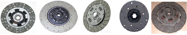
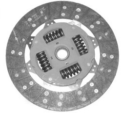
Fig.1A: Clutch Friction Disc
In a car, you need a clutch because the engine spins all the time, but the car’s wheels do not when at rest. Wheel can move only by the application of gear. But without application of clutch if one applies gear to run the wheel, the engine stops because engine is not designed to run the wheel directly when the car is at rest and it is the clutch which gently engages between the driving wheel and the engine crankshaft and initiates motion of driving wheel.
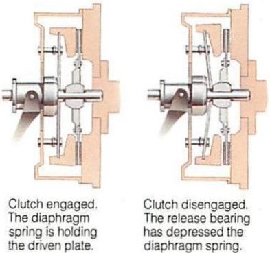
The clutch allows to smoothly engaging a spinning engine to a non-spinning transmission by controlling the slippage between them (Fig.2). The default state of the clutch is engaged – that is the connection between engine and gearbox is always “on” unless the driver presses the clutch pedal and disengages it. If the engine is running with clutch engaged and the transmission in neutral, the engine spins the input shaft of the transmission, but no power is transmitted to the wheels.
Clutch lining is made with NBR formulation,containing several ingredients and it basically acts like the pads on the brakes. Clutch lining is the surface of the clutch that does the grabbing. Clutch linings are a type of friction material, similar to rubberized brake linings, such that during application, there is smooth friction and less noise. They have a much different function, however than brake linings because unlike brake, a clutch is used to transfer the motion of one mechanical component to another by keeping two surfaces in contact. The clutch lining is what prevents these two surfaces from slipping.
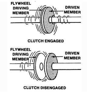
Fig.2: Clutch Engaged and Disengaged
Today’s clutch linings are usually made from fiberglass, Kevlar textiles, some type of metal (copper, steel etc.), reinforcing carbon, graphite, silicates etc. bonded by an oil resistant elastomer, preferably, NBR.
Throughout most of the 20th century however, clutch linings were made from asbestos, which provides superior cushioning and better wear than the modern materials currently in use today.
Use of Asbestos has been restricted in developed countries due to toxic gas generation in use.
Fig.3: Typical clutch components
A clutch is a mechanical device that engages and disengages the power transmission, especially from driving shaft to driven shaft (Fig.2). Clutches are used whenever the transmission of power or motion must be controlled either in amount or over time.
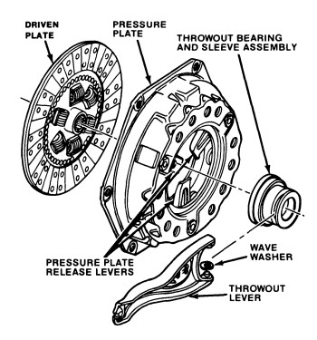
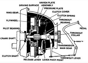
A clutch is a subcomponent of a car’s manual transmission system that engages and disengages the engine to the gearbox and transfers torque to the vehicle’s transmission in split-seconds. The clutch is a metal disc that directs the flow of power between the engine and the transmission along with the pressure plate and the flywheel.
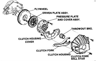
The various components necessary to deliver power to the drive wheels are the flywheel, pressure plate, clutch plate, release bearing, control linkages and the transmission. The modern clutch has four main components: the cover plate (which incorporates a diaphragm spring), the pressure plate, the driven plate, and the release bearing (Fig.3).
Fig.4: Functioning of Diaphragm Spring
The cover plate is bolted to the flywheel, and the pressure plate exerts pressure on the driven plate through the diaphragm spring or through coil springs on earlier cars.The driven plate runs on a splined shaft between the pressure plate and flywheel. It is faced on each side with a friction material which grips the pressure plate and flywheel when fully engaged, and can slip by a controlled amount when the clutch pedal is partially depressed, allowing the drive to be taken up smoothly.
When a car is moving under power, the clutch is engaged. A pressure plate bolted to the flywheel exerts constant force, by means of a diaphragm spring; on the driven plate (Fig.4). Earlier cars have a series of coil springs at the back of the pressure plate, instead of a diaphragm spring.
The driven (or friction) plate runs on a splined input shaft, through which the power is transmitted to the gearbox.
The plate has friction linings, similar to brake linings, on both its faces, which allows the drive to be taken up smoothly when the clutch is engaged.
When the clutch is disengaged (pedal depressed), an arm pushes a release bearing against the center of the diaphragm spring which releases the clamping pressure.The outer part of the pressure plate, which has a large friction surface, then no longer clamps the driven plate to the flywheel, so the transmission of power is interrupted and gears can be changed.
When the clutch pedal is released, the thrust bearing is withdrawn and the diaphragm-spring load once again clamps the driven plate to the flywheel to resume the transmission of power.
Some cars have a hydraulically operated clutch. Pressure on the clutch pedal inside the car activates a piston in a master cylinder, which transmits the pressure through a fluid-filled pipe to a slave cylinder mounted on the clutch housing.The slave-cylinder piston is connected to the clutch release arm.
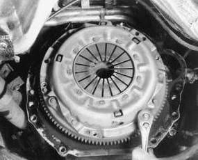
Fig.5: The clutch disc is installed between the pressure plate assembly and the flywheel
The release bearing is pushed hard against the diaphragm spring, either hydraulically or by a cable and lever, and releases spring load to interrupt power transmission. In a torque-controlled drill, for instance, one shaft is driven by a motor and the other drives a drill chuck. The clutch disc is practically installed between the pressure plate assembly and the flywheel(Fig.5).
The clutch connects the two shafts so they may be locked together and spin at the same speed (engaged), locked together but spinning at different speeds (slipping), or unlocked and spinning at different speeds (disengaged).
A transmission is used to vary the gear ratio for the best speed and power, and to provide for vehicle movement under the different conditions of starting, stopping, accelerating, maintaining speed and reversing.
Fig.6: Power Flow Thoroughly Synchronized Transmission
Power flow through a four-speed synchronized transmission is shown in Fig.6. As a rule, the power flow in high gear is usually straight through the transmission-input shaft to the main shaft, which would be locked together. In the reduction gears, the power flow is through the input shaft, to the cluster gear unit, and through the reduction gear to the main shaft.
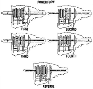
Fig.7: Cross-sectional view of a typical clutch, clutch pedal
Function of Clutch Plate: In a modern car with a manual transmission the clutch is operated by the left-most pedal using a hydraulic or cable connection from the pedal to the clutch mechanism.
On older cars the clutch might be operated by a mechanical linkage. Even though the clutch may physically be located very close to the pedal (Fig.7), such remote means of actuation are necessary to eliminate the effect of vibrations and slight engine movement, engine mountings being flexible by design.
With a rigid mechanical linkage, smooth engagement would be near-impossible because engine movement inevitably occurs as the drive is “taken up.”
The clutch is located between the engine and the gearbox, as disengaging it is required to change gear.
Although the gearbox does not stop rotating during a gear change, there is no torque transmitted through it, thus less friction between gears and their engagement dogs.
Fig.8: Typical clutch hydraulic actuating system components
The output shaft of the gearbox is permanently connected to the final drive, then the wheels, and so both always rotate together, at a fixed speed ratio. With the clutch disengaged, the gearbox input shaft is free to change its speed as the internal ratio is changed. Any resulting difference in speed between the engine and gearbox is evened out as the clutch slips slightly during re-engagement.
Hydraulic clutch activation systems consist of a master and a slave cylinder (Fig.8). When pressure is applied to the clutch pedal (the pedal is depressed), the pushrod contacts the plunger and pushes it up the bore of the master cylinder. During the first 1/32 in. (0.8 mm) of movement, the center valve seal closes the port to the fluid reservoir tank and as the plunger continues to move up the bore of the cylinder, the fluid is forced through the outlet line to the slave cylinder mounted on the clutch housing.

As fluid is pushed down the pipe from the master cylinder, this in turn forces the piston in the slave cylinder outward. A push-rod is connected to the slave cylinder and rides in the pocket of the clutch fork. As the slave cylinder piston moves rearward the push-rod forces the clutch fork and the release bearing to disengage the pressure plate from the clutch disc.
On the return stroke (pedal released), the plunger moves back as a result of the return pressure of the clutch. Fluid returns to the master cylinder and the final movement of the plunger lifts the valve seal off the seat, allowing an unrestricted flow of fluid between the system and the reservoir.
A piston return spring in the slave cylinder pre-loads the clutch linkage and assures contact of the release bearing with the clutch release fingers at all times. As the driven disc wears, the diaphragm spring fingers move rearward forcing the release bearing,fork and pushrod to move.
This movement forces the slave cylinder piston forward in its bore, displacing hydraulic fluid up into the master cylinder reservoir, thereby providing the self-adjusting feature of the hydraulic clutch linkage system.
In the simplest application, clutches connect and disconnect two rotating shafts (drive shafts or line shafts). In these devices, one shaft is typically attached to an engine or other power unit (the driving member) while the other shaft (the driven member) provides output power for work. While typically the motions involved are rotary, linear clutches are also possible.
Fig.9: Determining Gear Ratio
How the Manual Transmission Works: The internal combustion engine creates a twisting motion or torque, which is transferred to the drive wheels. However, the engine cannot develop much torque at low speeds; it will only develop maximum torque at higher speeds. The transmission, with its varied gear ratios, provides a means of providing this low torque to move the vehicle. The transmission gear ratios allow the engine to be operated most efficiently under a variety of driving and load conditions. Using gear ratios, the need for extremely high engine rpm at high road speeds is avoided.
The modern transmission provides both speed and power through selected gear sizes that are engineered for the best all-around performance.
A power (lower) gear ratio starts the vehicle moving and speed gear ratios keep the vehicle moving.
By shifting to gears of different ratios, the driver can match engine speed to road conditions.
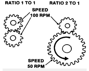
Gear Ratios can be found by dividing the number of teeth on the smaller gear into the number of the teeth on the larger gear (Fig.9).
To obtain maximum performance and efficiency, gear ratios are engineered to each type of vehicle, dependent upon such items as the size of the engine, the vehicle weight and expected loaded weight, etc.
The gear ratio can be determined by counting the teeth on both gears. For example, if the driving gear has 20 teeth and the driven gear has 40 teeth, the gear ratio is 2 to 1. The driven gear makes one revolution for every two revolutions of the drive gear. If the driving gear has 40 teeth and the driven gear 20 teeth, the gear ratio is 1 to 2. The driven gear revolves twice, while the drive gear revolves once.
The transmissions used today may have four, five or six speeds forward, but all have one speed in reverse. The reverse gear is necessary because the engine rotates only in one direction and cannot be reversed. The reversing procedure must be accomplished inside the transmission.
By comparing gear ratios, you can see which transmission transmits more power to the drive wheels at the same engine rpm. The five-speed transmission’s low or first gear with a ratio of 3.61 to 1 means that for 3.61 revolutions of the input or clutch shaft (coupled to the engine by the clutch), the output shaft of the transmission will rotate once. This provides more power to the drive wheels, compared to the four-speed transmission’s low gear of 2.33 to 1.
When the transmission is shifted into the high gear in the four-speed transmission, and fourth gear in the five-speed transmission, the gear ratio is usually 1 to 1 (direct drive). For every rotation of the engine and input shaft, the output shaft is rotating one turn.
Fifth gear in a five-speed transmission is usually an overdrive. This gear is used for higher speed driving where very little load is placed on the engine. This gear ratio provides better economy by lowering the engine RPM to maintain a specific speed. The input shaft rotates only 0.87 of a turn, while the output shaft rotates one revolution, resulting in the output shaft rotating faster than the input shaft.
Manufacturing of Clutch Plates: Featuring weight reduction from making thinner clutches and cost reduction arising from the change in manufacturing processes, “less machining” has enabled to introduce unmanned production line through the elimination of unnecessary cutting and machining. This has obvious advantages for large-volume production.Various materials have been used for the disc-friction facings, including asbestos in the past. Modern clutches typically use a compound organic resin with copper wire facing or a ceramic material. Ceramic materials are typically used in heavy applications such as racing or heavy-duty hauling, though the harder ceramic materials increase flywheel and pressure plate wear.
Modern clutch development focuses its attention on the simplification of the overall assembly and/or manufacturing method. For example drive straps are now commonly employed to transfer torque as well as lift the pressure plate upon disengagement of vehicle drive.
With regard to the manufacture of diaphragm springs, heat treatment is crucial. Laser welding is becoming more common as a method of attaching the drive plate to the disc ring with the laser typically being between 2-3KW and a feed rate 1m/minute. Figure 6 The clutch pressure plate assembly is bolted to the flywheel on the back of the engine.
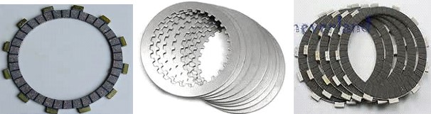
Fig.10: Motorcycle Clutch Plates
Motorcycles typically employ a wet clutch with the clutch riding in the same oil as the transmission. These clutches are usually made up of a stack of alternating plain steel and friction plates(Fig.10).
Some plates have lugs on their inner diameters that lock them to the engine crankshaft. Other plates have lugs on their outer diameters that lock them to a basket that turns the transmission input shaft. A set of coil springs or a diaphragm spring plate force the plates together when the clutch is engaged.
On motorcycles the clutch is operated by a hand lever on the left handlebar. No pressure on the lever means that the clutch plates are engaged (driving), while pulling the lever back towards the rider disengages the clutch plates through cable or hydraulic actuation, allowing the rider to shift gears or coast. Racing motorcycles often use slipper clutches to eliminate the effects of engine braking, which, being applied only to the rear wheel, can cause instability.
Compounding: There are basically two types of friction material used for clutch lining. These are organic and metallic. The organic is best for all around use. The metallic is preferred by some for severe duty applications but requires high spring pressures and is hard on the flywheel and pressure plate friction surfaces.
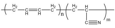
Clutch plate will invariably compounded with nitrile Rubber (NBR) to take care of contamination due to lubricants grease in the service condition. An important factor in the properties of NBR is the ratio of acrylonitrile groups to butadiene groups (Fig.11)in the polymer backbone, referred to as the ACN content.
Fig.11: Chemical structure of NBR
The lower the ACN content, the lower the glass transition temperature; however, the higher the ACN content, the better resistance the polymer will have to nonpolar solvents (mineral oil, petroleum oils, propane, kerosene, and diesel fuel). Most applications requiring both solvent resistance and low temperature flexibility require an ACN content of 33%.
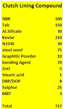
Table-1: Clutch Lining Compound
The uses of nitrile rubber include disposable non-latex gloves, automotive transmission belts, hoses, O rings, gaskets, oil seals, V belts, synthetic leather, printer’s form rollers, and as cable jacketing etc. Most importantly, it is also used in clutch lining and brake pad lining. Higher acrylonitrile contents increase solvent resistance but decrease low-temperature flexibility , therefore. NBR with ACN content of 33% will be perfect choice for clutch plate rubber compounding.
In brake pads, the metal is cut into shape separately and then the rubberized liner is added with glue or bonded with rubber metal bonding.In clutch lining the metallic luster is made by steel or copper wire. Rubber-metal bonding with copper is much better than steel, yet, due to higher cost of copper, steel wire is preferred in most cases.
Fig.12: Freshly cured clutch Plate

Including NBR which acts as binder of high volume of fillers like fiberglass, Kevlar, some type of metal wool (copper,steeletc), reinforcing carbon, graphite, silicates etc. (Table-1).
Use of Asbestos has been restricted in developed countries due to toxic gas generation and it is replaced by chopped Kevlar fiber instead. Rubberized metallic clutch plate is made in five steps.
First the master batch is made adding all ingredients other than curatives (Table-1).The mixed rubber are then dissolved in toluene. The mother batch is generally viscous. Around 15% of total solid content is made in a separate container by diluting the mother batch with solvent (toluene).
Fig.13 :Clutch Plate with Spring
Here the desired dose of sulphur and accelerators are added and mixed well to make the final rubber solution.
From the creel room different wire having different diameter (as per the strength requirement of the plate) is passed through the rubber solution and they are passed onward through hot air to dry up solvent before they are wind up on spool with desired diameter. Number of turn on the spool depends on the weight and thickness of the of the finished clutch plate.
These rubberized coiled metallic wire is then compressed in a heated hydraulically operated compression molding press, having auto bumping facility to make the metallic clutch plate. During molding sufficient number of bumping is given on the mold to avoid any air entrapment that will be discarded as off-spec material.
Fig.14: The entire Assembly of Clutch Plate
Freshly cured clutch Plate (Fig.12), which will have friction material riveted to each side, is then trimmed off after cooling and then other accessories are added after trimming the plate to final finish on cooling (Fig.13).
The major accessories attached are metallic springs, that can provide high spring pressures and is hard on the flywheel and pressure plate friction surfaces.
The entire clutch assembly is made when the clutch plated is attached with flywheel and Pressure Plate (Fig.14).